Large Core Custom EE64 High Frequency Transformer Low DCR Stable
Inverters
Low DCR Stable Inverters
The values below are common international buyer inquiry references
and starting points for engineering discussion. They are not fixed
or guaranteed ratings for every EE64 transformer. Final
requirements are confirmed through the approved specification,
drawing, material system, and customer sample-validation process.
| Industry | Typical Application | Typical Input Requirement | Typical Output Requirement | Typical Power Inquiry | Frequency | Key Parameters Evaluated | Safety and Environmental Focus | Available Customization |
|---|
| Industrial power supplies | Main transformer for isolated AC DC and DC DC converters | Switched excitation from rectified 85 V to 265 V AC or a specified
DC bus | Application-specific isolated output after rectification | Approximately 200 W to 1200 W | Commonly 20 kHz to 200 kHz | Flux density inductance turns ratio leakage DCR AC loss insulation
and temperature rise | Creepage clearance surge pollution degree flammability and
enclosure temperature | Ferrite grade gap foil or litz winding interleaving shield outputs
terminals and thermal design |
| Emergency power and UPS | Inverter transformer battery converter and charger stage | 24 V 48 V 72 V or higher customer-defined DC bus | Isolated high-voltage or low-voltage output | Approximately 300 W to 1500 W | Commonly 20 kHz to 150 kHz | Peak current saturation leakage DCR copper loss core loss and
thermal balance | Standby operation surge fault conditions and thermal endurance | Parallel conductors foil precision gap center tap shield insulation
busbars and sensors |
| Energy storage systems | PCS transformer and bidirectional battery converter | Battery or high-voltage DC link with defined bidirectional waveform | Isolated DC-link battery or auxiliary output | Approximately 300 W to 2000 W | Commonly 20 kHz to 200 kHz | Flux balance leakage DCR AC resistance capacitance saturation and
hotspot temperature | High-voltage separation transients vibration and traceability | Symmetrical winding low-capacitance design foil litz shield gap
busbars potting and sensors |
| EV charging equipment | Isolated DC DC stage and power-module transformer | PFC DC link or specified high-voltage or low-voltage bus | Isolated charging bus or auxiliary output | Approximately 300 W to 2000 W | Commonly 30 kHz to 200 kHz | Leakage capacitance AC resistance insulation temperature rise and
consistency | Charger insulation surge humidity vibration and traceability | Resonant leakage target reinforced insulation foil litz leads
busbars and potting |
| Industrial battery chargers | Main transformer for forklift AGV marine and stationary chargers | Rectified mains or battery-side DC bus | Customer-specified charging output after rectification | Approximately 200 W to 1500 W | Commonly 20 kHz to 150 kHz | Turns ratio current DCR AC loss leakage efficiency contribution and
temperature rise | Surge insulation cooling and protective-device coordination | Center-tapped secondary foil litz shield insulation sensors and
terminals |
| Industrial drives and robotics | Drive auxiliary supply and high-power isolated conversion | Rectified mains DC link or specified DC input | Isolated DC bus or multiple control outputs | Approximately 150 W to 1000 W | Commonly 20 kHz to 200 kHz | Saturation capacitance leakage DCR EMI temperature rise and
vibration | Industrial temperature transients pollution degree and insulation | Low-capacitance winding shield multiple outputs leads brackets and
impregnation |
| Telecom and data center power | High-power isolated DC DC and server power modules | 48 V DC bus or high-voltage PFC bus | 12 V 24 V 48 V or application-specific output | Approximately 200 W to 1500 W | Commonly 50 kHz to 250 kHz | AC and DC resistance leakage capacitance core loss and thermal path | Isolation EMC high operating duty traceability and thermal cycling | Foil or litz winding interleaving shield terminals busbars and
tightened tolerances |
| Renewable energy inverters | Solar wind and distributed-energy converter stage | High-voltage DC link or renewable-energy bus | Isolated DC link battery interface or auxiliary output | Approximately 300 W to 2000 W | Commonly 20 kHz to 200 kHz | Wide input range flux balance saturation leakage DCR capacitance
and thermal margin | Outdoor surge humidity thermal cycling and high-voltage separation | Reinforced insulation low-capacitance design foil litz shield
sensors and potting |
| Medical and laboratory power | High-power isolated supply for diagnostic and analytical equipment | Customer-defined PFC bus or DC converter input | Application-specific isolated outputs | Approximately 150 W to 800 W | Commonly 30 kHz to 200 kHz | Creepage clearance dielectric strength capacitance EMI and thermal
performance | Coordination with applicable end-equipment requirements | Reinforced insulation low-capacitance winding shield sensors and
documented tests |
Major customizable parameters include topology, input range, output
voltage and current, operating power, switching frequency, duty
cycle, primary inductance, magnetizing current, turns ratio, air
gap, peak and RMS current, saturation margin, leakage inductance,
DCR, AC winding resistance, capacitance, ferrite material, copper
foil, litz or parallel-wire construction, winding sequence,
shielding, insulation, terminals, leads, busbars, mounting,
temperature sensors, and test criteria.
Product Overview
The EE64 is a large high-frequency ferrite transformer platform
intended for medium- and high-power switched-mode power supplies,
isolated DC DC converters, inverters, battery chargers,
energy-storage systems, industrial drives, renewable-energy
equipment, and other power-electronics applications.
The supplied image shows a large rectangular magnetic assembly with
substantial visible multi-strand windings, layered insulation, and
extended insulating support plates. The construction appears
intended for higher-current power conversion, but the exact
conductor type, bobbin, ferrite material, air gap, terminations,
shielding, and mechanical arrangement cannot be confirmed from the
image alone.
EE64 identifies the approximate ferrite-core platform and does not
define a fixed power rating. Final capability depends on:
- Converter topology
- Input-voltage range
- Switching waveform and frequency
- Duty cycle
- Flux-density limit
- Ferrite grade
- Air gap
- Winding conductor
- Skin and proximity effects
- Leakage target
- Cooling method
- Ambient temperature
- Insulation system
- Mounting
- Permitted hotspot temperature
Required development information includes topology, input range,
switching frequency, duty cycle, output voltage and current,
continuous and peak power, primary inductance, turns ratio, current
waveforms, leakage target, DCR and AC resistance limits,
capacitance target, isolation voltage, creepage, clearance,
cooling, dimensions, terminals, applicable requirements, and test
plan.
Product Construction
| Construction Item | EE64 Customization Reference |
|---|
| Magnetic platform | EE64 ferrite-core platform or approved equivalent selected
according to frequency waveform flux density losses and thermal
requirements |
| Core material | Power ferrite selected according to switching frequency waveform
temperature and core-loss target |
| Core fixing | Tape adhesive clamp bracket or approved mechanical system |
| Winding former | Standard bobbin split bobbin custom former or bobbinless
arrangement |
| Winding conductor | Enameled wire parallel conductors litz wire copper foil or combined
conductor system |
| Visible winding | The image shows substantial orange multi-strand winding bundles but
exact specifications require confirmation |
| Winding arrangement | Layered interleaved sandwich sectional or separated structure |
| Insulation system | Film tape barriers sleeving margins spacers and lead insulation |
| Shielding | Optional electrostatic shield flux band or external magnetic shield |
| Air gap | Ungapped distributed-gap or precision-gapped construction |
| Terminations | Flying leads copper tabs terminals busbars lugs or customized
connectors |
| Mechanical support | Insulating plates spacers brackets core restraints and winding
reinforcement |
| Impregnation and potting | Varnish partial potting encapsulation or thermally conductive
compound |
| Temperature monitoring | Optional thermostat thermistor RTD or other sensor |
| Traceability | Custom model winding identification date code lot code and customer
label |
Final core outline, assembly height, support-plate dimensions,
winding clearances, terminal positions, mounting points, and
tolerances must be confirmed by the approved drawing.
Product Characteristics
Large Core Power Conversion Platform
The EE64 platform provides a larger magnetic cross-section and
winding window than smaller EE structures. This can support
higher-power inquiries, but no power value is guaranteed without a
complete electrical and thermal review.
High Current Winding Options
Copper foil, litz wire, parallel conductors, multi-strand wire,
copper tabs, and busbars can be considered to manage RMS current,
DCR, skin effect, proximity loss, current sharing, and termination
temperature.
Controlled Leakage Inductance
Interleaving can reduce leakage, while deliberate winding
separation can create a specified resonant leakage value. Leakage
must be balanced against capacitance, insulation spacing,
manufacturability, and thermal performance.
Low DCR and AC Resistance Development
Conductor cross-section, strand size, foil thickness, parallel
paths, layer arrangement, winding length, and termination design
can be reviewed together. DCR alone does not represent total
high-frequency winding loss.
EMI and Capacitance Options
Winding sequence, shielding, sectional construction, interwinding
spacing, and return paths can be customized to support
common-mode-noise objectives. EMC performance must be verified in
the complete converter.
Thermal Management Support
Core loss, copper loss, hotspots, insulation thermal conductivity,
airflow, conduction cooling, potting, mounting, and sensor position
can be reviewed as one thermal system.
Mechanical Reinforcement
Controlled core fixing, winding support, lead strain relief,
insulation protection, and mounting can be developed for vibration,
transportation, and production handling.
Applications
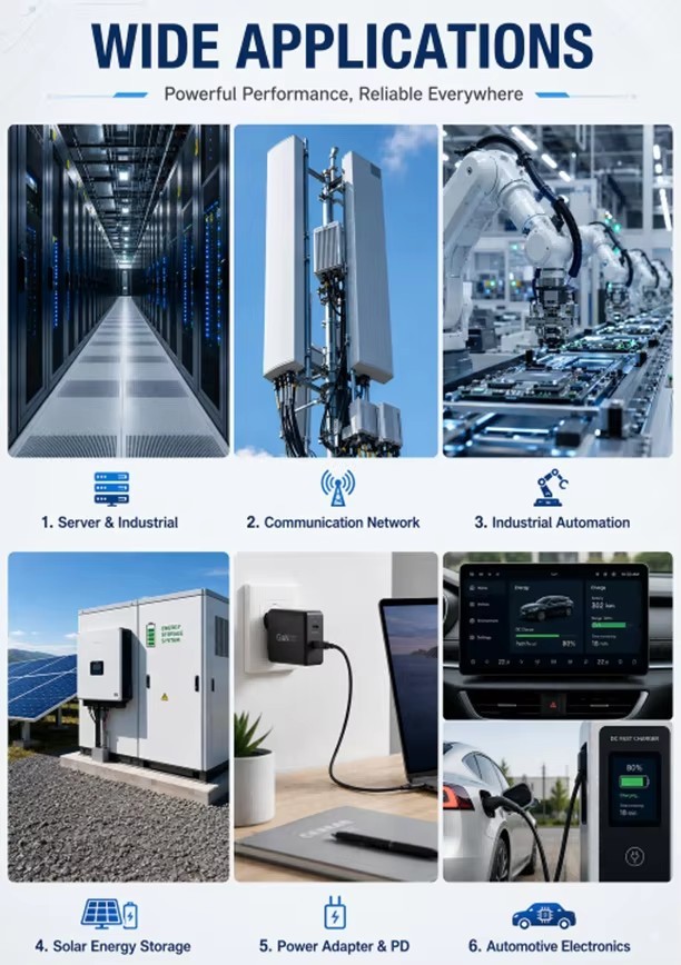
- Industrial high-power switched-mode power supplies
- Emergency-power and UPS inverters
- Energy-storage PCS converters
- Bidirectional battery converters
- Solar and renewable-energy inverters
- Industrial battery chargers
- EV charging equipment
- High-power isolated DC DC converters
- Telecom rectifiers and data-center power modules
- Industrial motor drives and robotics
- Welding and industrial power equipment
- Isolated gate-drive and auxiliary power systems
- Medical and laboratory power equipment
- Full-bridge half-bridge push-pull and resonant converters
Suitability must be confirmed according to the actual electrical,
thermal, mechanical, environmental, and safety conditions.
Quality Control
Incoming Material Inspection
Inspection may cover ferrite cores, winding formers, copper foil,
litz or multi-strand wire, insulation films, tape, barriers,
sleeving, terminals, busbars, adhesives, potting materials,
sensors, support plates, labels, and supplier documentation.
Design Review
Engineering review can evaluate topology, frequency, volt-second
conditions, flux density, magnetizing inductance, peak current,
saturation margin, core loss, turns ratio, conductor selection,
skin and proximity effects, winding fill, leakage, capacitance,
DCR, insulation, creepage, clearance, hotspots, and cooling.
In Process Control
Controls may include turns counting, winding direction, conductor
preparation, parallel-path arrangement, foil insulation, winding
sequence, tension, interlayer insulation, lead routing, terminal
joining, shield installation, gap control, core assembly, sensor
placement, impregnation, and potting.
Electrical Testing
Tests may include:
- Inductance
- Turns ratio and polarity
- Winding DCR
- Leakage inductance
- Dielectric strength
- Insulation resistance
- Interwinding capacitance
- Shorted-turn screening
- Functional converter testing
Test frequency, voltage, current, bias, limits, duration, sampling
level, and testing frequency must follow the approved test plan.
Mechanical Inspection
Inspection may cover core dimensions, overall height, support
plates, winding clearances, conductor routing, terminals, busbars,
insulation coverage, core fixing, sensor location, labels, mounting
compatibility, and workmanship.
Sample Validation
Samples should be tested in the customer's converter across minimum
and maximum input, no load, full load, peak load, frequency range,
startup, transient, fault, ambient temperature, and cooling
conditions.
Validation may include waveforms, flux balance, peak current,
leakage behavior, regulation, efficiency contribution, hotspot
temperature, EMI, vibration, and insulation testing.
Traceability
Material lots, ferrite batches, conductor lots, winding batches,
gap records, terminal-joining records, test results, and
engineering changes can be controlled.
Company Profile
Chipsen specializes in the development and manufacturing of custom
magnetic components for industrial equipment power electronics
automation systems and electrical control applications.
The product range includes high-frequency transformers
low-frequency transformers planar transformers power inductors
high-current inductors toroidal inductors common-mode chokes EMI
filter magnetics wireless charging coils custom coils and
non-standard magnetic components.
Chipsen supports drawing-based development sample-based replacement
development and application-requirement design. Engineering
discussions can cover low DCR leakage inductance EMI insulation
temperature rise winding structure footprint pinout terminals
protection devices and production-testing requirements.
The objective is to provide evaluation-ready samples and a clearly
defined specification before production approval.
Why Choose Chipsen
Application Specific Customization
The EE64 can be developed around topology, input range, frequency,
power profile, current waveform, leakage target, insulation
architecture, cooling, terminals, mounting, and operating
environment.
OEM and ODM Support
Support is available for new designs, drawing-based manufacturing,
sample-based replacement development, and application-based
engineering review.
Drawing and Sample Based Development
Chipsen can review an existing drawing or sample. Converter
waveforms, operating conditions, and acceptance limits should also
be provided.
Engineering Collaboration
Engineering discussions can address inductance, turns ratio,
leakage, DCR, AC resistance, gap, conductor system, capacitance,
EMI, saturation margin, insulation, hotspots, cooling, terminals,
and mounting.
Flexible Prototype Support
Prototype quantities and schedules are reviewed according to
material availability, tooling, terminal requirements, complexity,
and specification completeness. No verified MOQ is visible in the
image.
Responsive Project Handling
Quotation and sample timing are confirmed after complete
information is received and the specification, materials, tooling,
and thermal-validation requirements are reviewed. No verified
timing is visible in the image.
Warranty Support
Warranty terms are confirmed according to application, operating
conditions, validation status, and the written supply agreement. No
warranty period is visible in the image.
Controlled Specification Process
The approved drawing, electrical specification, material system,
validation results, and test plan form the basis for production
control.
Mechanical Integration Support
Core outline, winding clearances, support plates, terminals,
busbars, leads, mounting points, sensors, potting, and labeling can
be reviewed for the customer assembly.
Frequently Asked Questions
Is EE64 a fixed power rating?
No. EE64 identifies an approximate ferrite-core platform. Power
capability depends on topology, waveform, frequency, flux density,
conductor design, cooling, insulation, and temperature rise.
What information is required for quotation?
Please provide topology, input range, frequency, duty cycle, output
voltage and current, continuous and peak power, inductance, turns
ratio, current waveforms, leakage and resistance limits, isolation,
cooling, dimensions, terminals, demand, and tests.
Which converter topologies can be supported?
Full-bridge, half-bridge, push-pull, forward, resonant,
bidirectional, and other customer-specified topologies may be
considered.
Can copper foil or litz wire be used?
Yes. Copper foil, litz wire, parallel wire, or combined conductors
may be considered according to frequency, current, skin effect,
winding space, insulation, and termination requirements.
Can multiple outputs be added?
Yes, when winding space, regulation, current sharing, insulation,
and thermal limits permit.
Can primary inductance and air gap be customized?
Yes. They can be developed around topology, magnetizing current,
peak current, stored energy, saturation margin, and tolerance.
Can leakage inductance be controlled?
Yes. Leakage can be minimized or deliberately designed for a
resonant target through winding geometry, separation, interleaving,
and insulation.
Can DCR and AC resistance be reduced?
They can be optimized through conductor cross-section, strand
diameter, foil thickness, parallel paths, winding length, layer
arrangement, and terminations.
Can an electrostatic shield be added?
Yes. A shield may be added when space, capacitance, insulation, and
thermal conditions permit.
Are reinforced-insulation options available?
Reinforced insulation may be developed using suitable spacing,
barriers, films, tape, sleeving, or specialized insulated
conductors.
Can terminals leads and busbars be customized?
Yes. Copper tabs, lugs, busbars, flying leads, connectors, strain
relief, and mounting can be customized.
Can temperature sensors be installed?
A thermostat, thermistor, RTD, or other sensor may be included when
required.
Can Chipsen develop a replacement from a sample?
Yes. Sample-based development can include mechanical measurement
and electrical characterization.
What tests are available?
Tests may include inductance, turns ratio, polarity, DCR, leakage,
dielectric strength, insulation resistance, capacitance,
shorted-turn screening, dimensions, thermal testing, and
application validation.
Does it automatically comply with an IEC or UL standard?
No. It can be developed to support specified requirements, but
certification or end-product compliance is not automatic.
What is the MOQ?
MOQ is confirmed according to ferrite, conductor and terminal
availability, tooling, complexity, and production requirements.
What is the quotation and sample time?
Timing is confirmed after complete electrical, mechanical,
insulation, thermal, and commercial information has been reviewed.
What warranty is available?
Warranty terms are confirmed according to the application,
operating conditions, validation status, and written agreement.
The EE64 model or ferrite-core platform does not by itself define a
fixed power, voltage, current, frequency, insulation, or thermal
rating. Final performance is confirmed only through the approved
drawing, electrical specification, material system, test plan, and
customer sample-validation process.
Product Images


 EE64 EE65 PQ60 Planar Transformer High Power Density Low Leakage Isolation For DC DC Converter Power Supply

